Patent Drawing Examples: 15 Examples and What Each View Shows
Do you wonder why a patent application you've been reading is crowded with many pictures – front views, side views, exploded figures, cross-sections? Then this article is for you! The views in patent drawings are not just aesthetically pleasing but are designed for specific technical reasons. Choosing the wrong combination of views (or omission of a particular view) is one of the most common reasons of USPTO office actions and rejected applications.
In this article, we are going to consider 15 real examples of patent drawing views, explaining what each view depicts, in what cases it should be used and why it is expected by the examiner. Whether you prepare a utility patent for your invention or a design patent for your product design, knowledge of the above view types will help you (or your patent illustrator) submit a clear and legally sound application.
Before moving to the examples, let's understand the whole concept of the views' usage. Depending on the type of patent, drawings perform different functions:
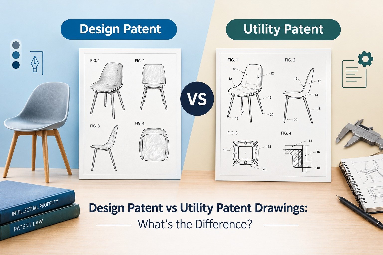
In a utility patent, drawings support the written description of an invention. They assist an examiner (and later a court, if applicable) in understanding how the invention is constructed and operates. The scope of legal protection is defined by the claims, but the drawings make it clearer for an examiner.
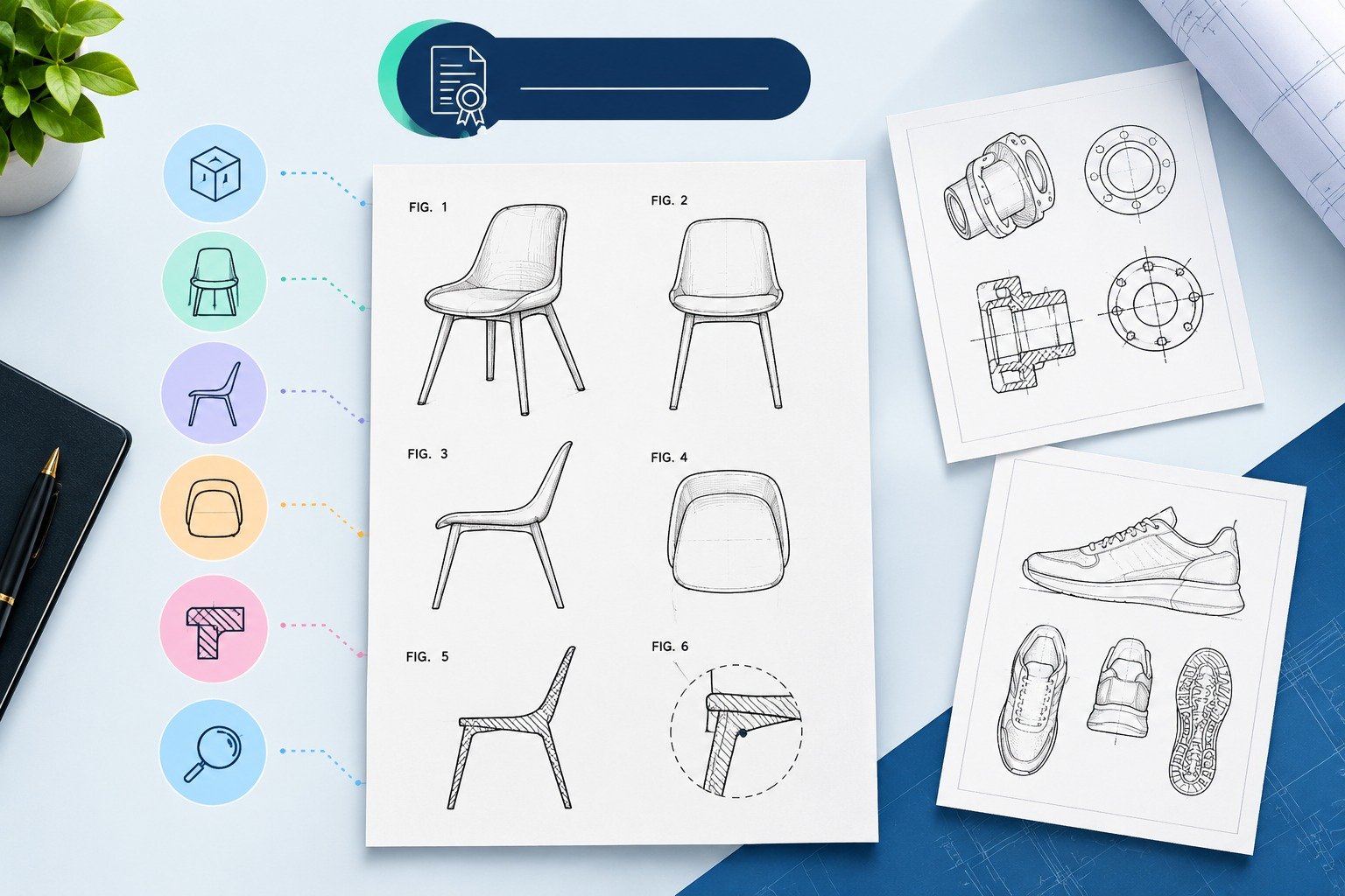
In a design patent, drawings define the scope of protection in themselves. There is no detailed description of the shape of an invention or its ornamental features, as the views are the invention. That is why design patent applications normally require a complete set of orthographic views (front, rear, top, bottom, left and right side) plus at least one perspective view, while in case of utility patents the situation is quite flexible.
There are specific requirements concerning the form of the views in accordance with the USPTO's drawing regulations under 37 CFR 1.84 (utility) and 37 CFR 1.152 (design). Before the formatting of the views, you should understand which views are necessary for your application. And here comes the list of 15 views and their functions.
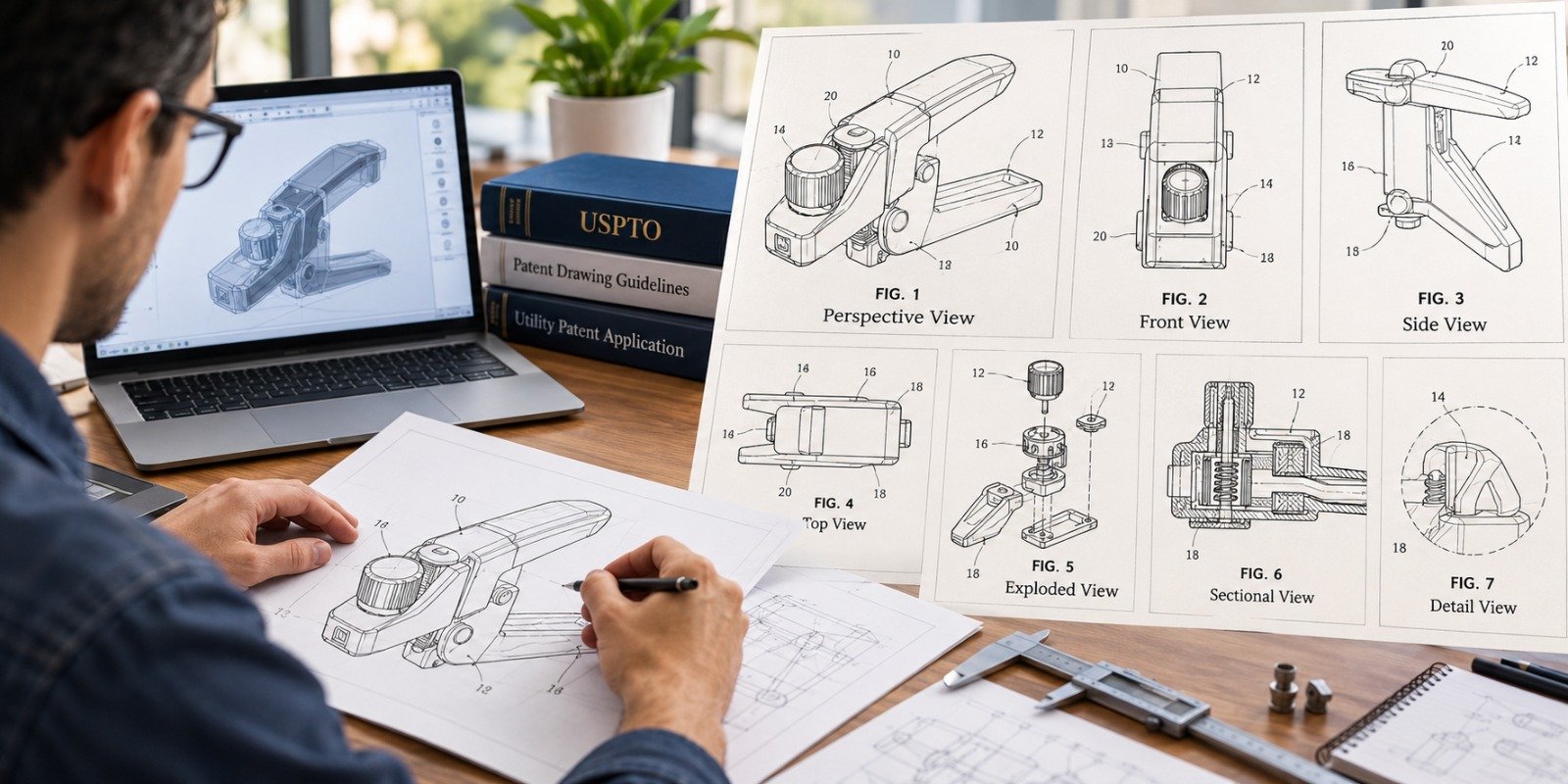
The front view is normally the core drawing of every patent application and is labeled as Figure 1 and represents the invention viewed from the front.
What it shows: Main silhouette, proportions and visible features of the invention from the most representative point of view.
When it is used: In virtually all design patent applications and in majority of utility patents where the overall shape or front-facing components play an important role (e.g. control panels, housings, product exterior).
Why it is important: Usually the examiner starts evaluating the invention from this view. In case of design patents, poor shading of the front view can lead to misunderstanding of the nature of the claimed invention.
The rear view is the mirror of the front view and represents the invention viewed from the rear.
What it shows: Rear features of the object – vents, connectors, hinges, mount points or simply the confirmation that the rear surface is free of ornamental features.
When it is used: Required in almost all design patent applications and in case of utility patents when the invention has the components facing the rear.
Why it is important: Lack of the rear view in design patent applications can result in "insufficient disclosure" rejection, since the examiner cannot understand whether the rear surface has additional protected ornamentation.
The top view, also known as the plan view, represents the invention viewed from the top.
What it shows: Silhouette of the object and the features on its upper surface – buttons, seams, patterns or the overall shape of the object.
When it is used: Standard view in design patents, commonly used in utility patents for objects having a horizontal working surface, control panel or the top-mounted component (e.g. a keyboard, an appliance lid or a tool upper housing).
Why it is important: Particularly in case of design patents, the top view depicts the curvature or contour lines linking the front and side views and, consequently, the inconsistency in this view can be the reason of rejection.
The bottom view is the mirror of the top view and represents the invention viewed from the bottom.
What it shows: Underside features like feet, vents, battery compartments, mounting hardware or the flat, plain surface.
When it is used: Required in design patent applications as the part of the complete set of views and in case of utility patents when the underside features are functionally relevant.
Why it is important: Even if the underside of a product is completely plain, depiction of the bottom view confirms to the examiner that there are no protected ornaments left out of the claims.
The left side view represents the invention viewed from the left side, at a 90-degree angle from the front view.
What it shows: Side profile or silhouette of the object, its thickness, depth and the side-mounted features.
When it is used: One of the standard orthographic views in design patents and in case of utility patents when the invention has the side profile features relevant to its function (e.g. a hinge mechanism, a lever or an internal component visible through the side panel).
Why it is important: The side views are the place where the curvature and contour lines from the front and top views should coincide precisely. Any discrepancy between these views can result in "new matter" or clarity objection.
The right side view depicts the same object from the opposite side.
What it shows: The right side features or whether the right side is identical to the left side – if not, both sides have to be depicted individually.
When it is used: Required view in case of design patents for the full disclosure in case the object is not genuinely symmetrical (then the explanation can be provided in the specifications, but it should be done very carefully).
Why it is important: Assuming symmetry and skipping this view can be an avoidable reason of rejection or delay in examination.
The perspective view, also known as isometric or 3D view, depicts the invention from some angled point of view so that several surfaces of the object are visible at once.
What it shows: More clear, three-dimensional idea of the object shape, its proportions and relation between its surfaces.
When it is used: Almost always required in case of design patents as the view that links all orthographic views and in case of utility patents as an introductory figure that provides an orientation before more detailed views are shown.
Why it is important: This view gives the chance for the human examiner, judge or competitor to visualize the invention rather than reconstruct it in mind from six flat orthographic views.
An exploded view represents separate components of an invention that are drawn separately in the order of their assembly and linked by dashed lines.
What it shows: The way how components are assembled, in which order they are assembled and how they are interrelated.
When it is used: Exclusive for utility patents for mechanical assemblies, electronics with internal components or products with removable components.
Why it is important: An exploded view is the clearest way to demonstrate the novelty in the invention in terms of interaction between the parts, which is often the heart of the utility patent claims. Besides, the exploded view makes examination simpler by visually separating parts that otherwise would be included in one drawing.
The cross-sectional view represents the invention "cut" on some defined plane, showing its internal structure with hatching (diagonal lines).
What it shows: The inner structure, internal chambers, passages, layers or mechanisms that are not visible from the outside.
When it is used: Common in case of utility patents for inventions having internal complexity (pumps, filters, multi-layer materials, containers with internal compartments, etc.), since its inside is the subject of innovation.
Why it is important: An invention cannot be disclosed properly without a cross-sectional view. Examiners rely on these views greatly to confirm the coincidence of the claimed internal structure and structure described in the specifications.
Almost the same as the cross-sectional view, but in this case the section is taken along the marked line of another figure (for instance, "Figure 4 is a sectional view taken along line 4-4 of Figure 2").
What it shows: Precise targeted internal view that corresponds to the exact point marked on some other figure rather than the general internal view.
When it is used: Used in case of utility patents when multiple internal cross-sections are required, and each one is clearly traced from another figure.
Why it is important: This labeling convention prevents the ambiguity when an invention has several internal features at different points of its length or height and without it the examiner (or any other person who reads the application) cannot understand from which point of the invention this internal view was taken.
The detail view magnifies some small but important part of the invention that is too small to be seen clearly in the main drawing.
What it shows: Magnified picture of a feature that is difficult to depict in a large-scale drawing such as a locking mechanism, texture, small connector, intricate joint or any other small but important feature.
When it is used: In both utility and design patents in case some feature is relatively small in comparison with the overall object but is essential for claims (utility patents) or the ornamental design (design patents).
Why it is important: Small and legally significant features can be misinterpreted or missed entirely without a detail view.
The broken-line view depicts some parts of the drawing that are not the part of the claimed invention using the dashed or dotted lines – usually the environmental context or some unclaimed portions of the design.
What it shows: The relation of the invention to its environment or the portions of the object that are claimed and those that are shown just for illustration purpose.
When it is used: Common in design patents, e.g. depiction of a phone case in broken lines around the claimed screen protector.
Why it is important: This view is one of the most misunderstood conventions in patent drawing. Confusion of solid and broken lines results in either expansion of the claim beyond what is intended or making the claim so small that competitors can design around it easily.
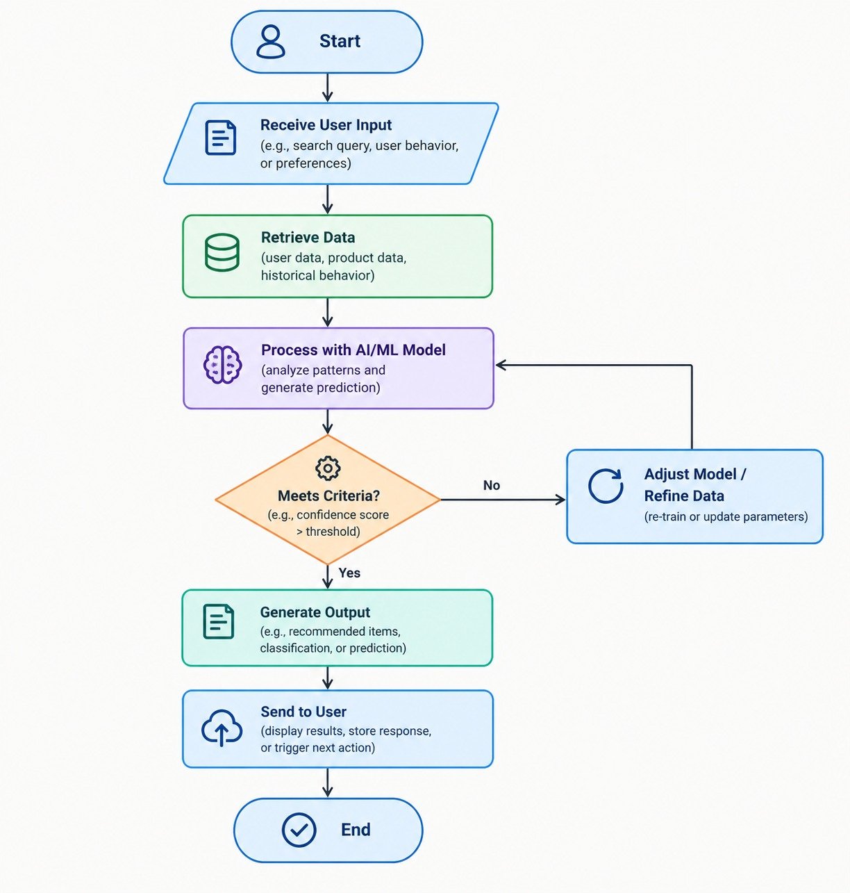
A flowchart uses boxes, arrows and decision points to represent a sequence of steps rather than the physical object.
What it shows: Logical or procedural flow of the process or sequence of steps of a process, algorithm, method or procedure. Used mostly in case of software-related inventions, business processes or manufacturing methods.
When it is used: Only in case of utility patents when the process (method) is claimed and there is no physical object to draw.
Why it is important: For process-based inventions the flowchart is one of the most important drawings in the application because it is often the only picture of the claimed invention.
The block diagram represents the components of a system and their connections without depicting their detailed physical structure.
What it shows: The relations between the functional units – a sensor, a processor, power supply and communication module.
When it is used: Common in case of utility patents involving electronics, software systems or complex multi-part systems when the relationships between components are more important than their physical structure.
Why it is important: The block diagram allows an applicant to depict the system level architecture without getting bogged down in mechanical details of the invention, which are not important.
The phantom view depicts the invention (or part of it) using the broken lines in its alternate position – for instance, the view of a hinge in its opened/closed position or a chair in its reclined/upright position.
What it shows: Range of motion or different positions of a design or mechanism, without creating a separate, fully claimed figure of the same.
When it is used: Both design and utility patents use this technique: the former in case the product has some moving parts and the latter when the depiction of the mechanism range of motion is needed.
Why it is important: This view allows disclosing information about the movement without expanding the set of drawings unnecessarily.
View Type | Primary Use | Usually Used In |
| Front View | Main silhouette from the front | Design & Utility |
| Rear View | Back-side features | Design & Utility |
| Top View | Upper surface and outline | Design & Utility |
| Bottom View | Underside features | Design & Utility |
| Left Side View | Side profile | Design & Utility |
| Right Side View | Opposite side profile | Design & Utility |
| Perspective View | 3D overall shape | Design & Utility |
| Exploded View | Component assembly order | Utility |
| Cross-Sectional View | Internal structure | Utility |
| Sectional View (along a line) | Targeted internal detail | Utility |
| Detail View | Magnified small feature | Design & Utility |
| Broken-Line (Environmental) View | Context vs. claimed portion | Design |
| Flowchart View | Process/method steps | Utility |
| Block Diagram | System component relationships | Utility |
| Phantom/Alternate Position View | Movement or alternate states | Design & Utility
|
Not every patent needs all 15 views described above – in fact, the inclusion of unnecessary views can clutter the application and can sometimes raise concerns regarding the scope of your claims. A few practical recommendations:
Experienced applicants can run into a few mistakes anyway:
No. Depending on the nature of the invention and patent type, you'll only use some subset of these views. For example, design patents would require 6 orthographic views and a perspective view, while utility patents will choose whatever combination of views would help best illustrate the invention (exploded view, sectional view, flowchart, etc.).
`
These two views are quite close in nature. While cross section is a simple illustration of the interior of an invention, the sectional view will be always labeled with "Taken along line XXXX of FIG. YYY" to indicate where exactly this view is taken.
In case of design patents, you can use photographs. However, for utility patents, the use of photographs is usually limited and requires a special petition to justify that a line drawing will be insufficient to illustrate the invention.
In case of design patents, drawings determine the scope of protection. Solid lines in drawings indicate claimed design elements, while the broken lines provide context or indicate parts not claimed in the design. Mixing these two will cause the applicant to unintentionally narrow or expand the scope of patent protection.
Inconsistency between views – if a certain feature is present in one drawing but not in another – is one of the most common causes of rejections issued by the USPTO based on lack of clarity and "new matter" support issues.
Each and every one of these 15 patent drawing examples is made to address a specific question that might be asked by an examiner (and, possibly, competitors in the future): What does it look like from different angles? How does it disassemble? What happens inside? How does it work? Choosing the right set of views (and presenting them in a correct manner) is probably the most practical way of strengthening a patent application before it even reaches an examiner.
If you're working on an application and unsure what set of views your invention requires, it is worth considering reviewing your disclosure by a patent professional. Correctly prepared set of drawings may help save a lot of time, effort, and money throughout the whole examination process.

At “The Patent Experts” our team specialises in turning complex concept and ideas into exact complaint patent drawings that meet the stringent guidelines of USPTO, EPO, WIPO among other major patent offices around the globe. With over 5+ years of experience, our team of skilled illustrators are efficient in producing high quality utility designs and trademark patent drawings. By combining cutting-edge technology with a deep understanding of global patent regulations, we ensure every drawing we create is ready for seamless submission and approval.
Quicks Links
Get in touch
Our phone number
Our email address
© 2026 The Patent Expert's All Rights Reserve
Made with ♥ by Website99