Utility Patent Drawing Views
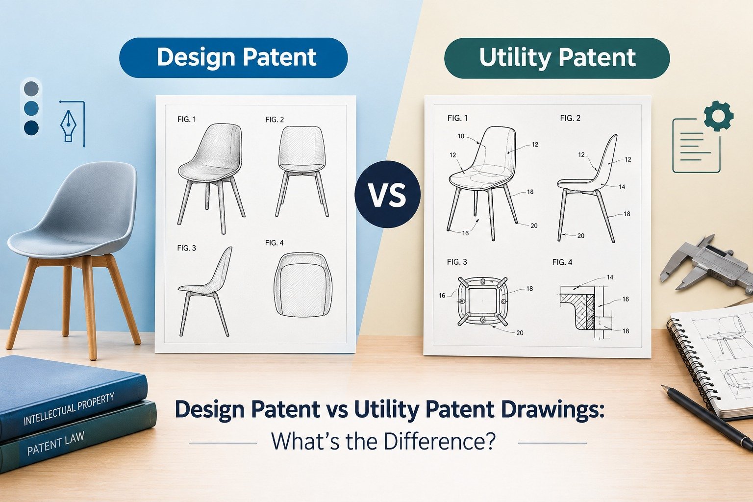
If you are preparing a utility patent application, one of your first questions would be pretty obvious but not always clear: How many drawings should I submit? No general answer would help you here since the idea “each utility patent should have six drawings” is false. The rules for utility patent drawings differ from these for design patents.
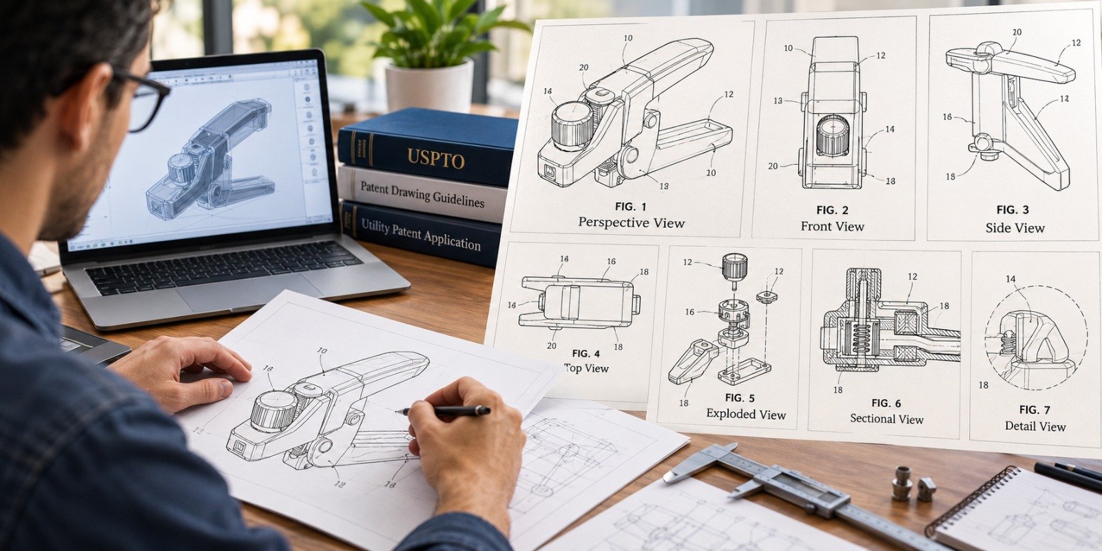
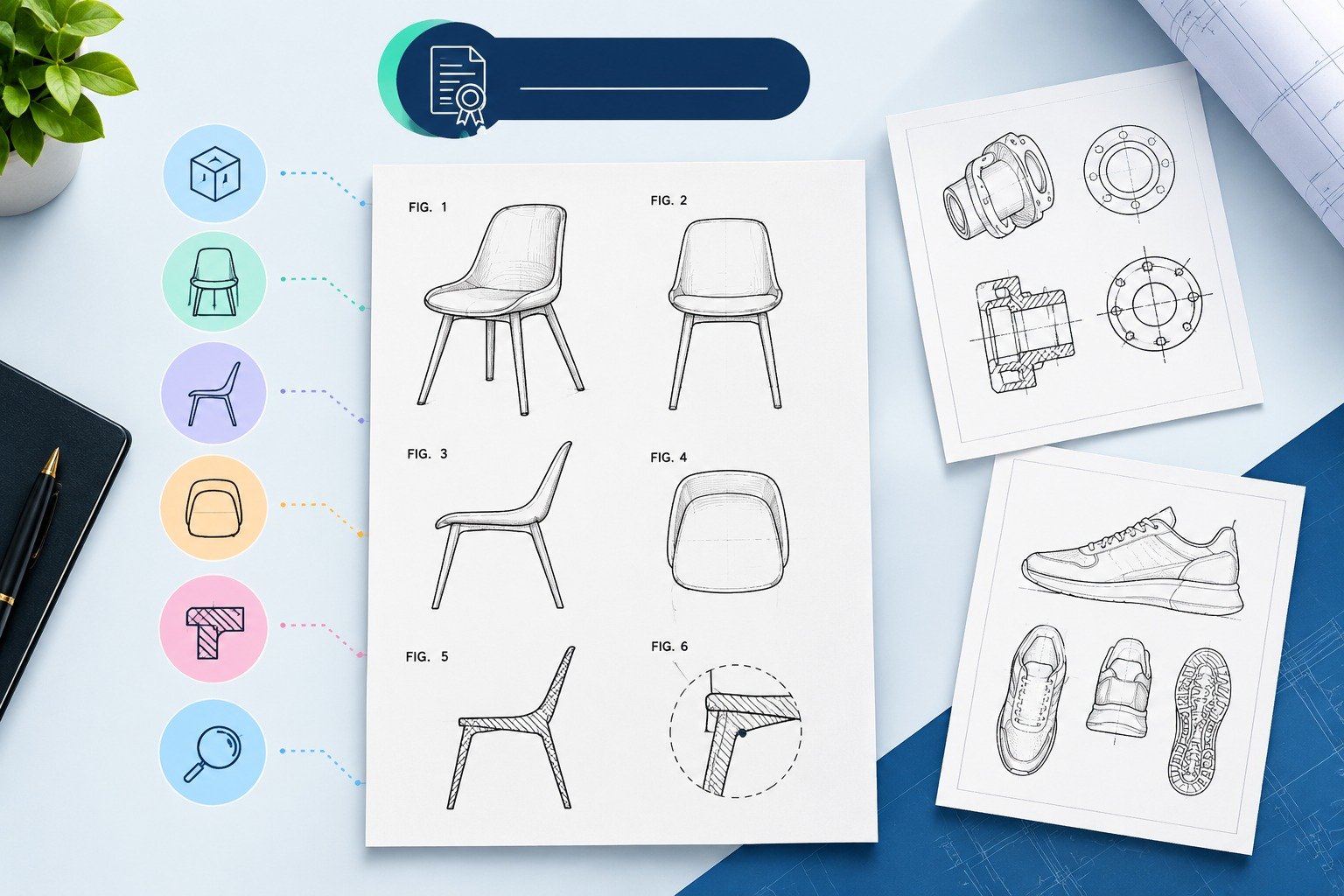
First of all, there is no fixed number of drawings that you have to submit along with your application – the number of the drawings depends on the kind of invention. According to the USPTO requirements, there should be enough number of drawings to enable a complete and thorough description of your invention. So you will need one drawing, several external views, a perspective drawing, an exploded view, cross-sections and detailed views of some parts of your invention.
It is not about the number of drawings; the idea is to ensure that a reader (patent examiner) understands your invention from these drawings and written description. This guide covers the most common utility patent drawing views, their purpose and USPTO requirements.
Patent drawings for utility patents are not restricted by a standard set of views that must be included for every invention.
The USPTO guidelines on how to draw state that there should be enough drawings to enable comprehension of the invention, which can include plan, elevation, section, perspective, and enlarged view. Other views such as exploded and partial view can also be used in case they are helpful in explaining the invention.
Some common drawings included in a useful mechanical invention are:
But this does not mean every application will include all these drawings.
Some simple inventions may need just two or three drawings while complex machines with moving parts might require more.
So the proper question to ask would not be:
“How many patent drawings do I need?”
It is:
“Which views are necessary to clearly disclose the features and operation of my invention?”
Patent drawings are not simply ornamental designs included in a patent application to improve its appearance.
In many utility patents, patent drawings are an integral part of the technical disclosure.
As stated by the USPTO, drawings need to be filed if drawings are needed to understand the subject matter for which the patent is sought. This rule applies to most machines, devices, articles of manufacture, systems, and structures.
Consider explaining a locking device, medical instrument, hinges, engine parts, adjustable brackets, or sophisticated consumer products by text only.
It might be technically feasible but becomes increasingly hard to comprehend quickly.
A properly chosen set of drawings will provide the reader with various viewpoints on the invention.
That is why choosing the correct views is just as important as drawing them accurately.
A perspective view shows the invention in three dimensions, allowing the viewer to see more than one surface at the same time.
For many mechanical and product-based inventions, this is one of the most useful figures in the entire drawing set.
A perspective view may show:
Instead of presenting the invention as a flat profile, perspective views help the reader understand its overall form.
Perspective views are especially valuable for inventions such as:
Let us assume that an inventor has created a novel adjustable clamping device.
A front view may depict the jaws, whereas a side view may depict the adjusting system. Perspective view will enable the reader to instantly recognize how these components fit together.
A single view is also useful in that it could serve as an illustration on the cover page of a patent application or patent document.
This is the reason why perspective view is quite useful as an initial drawing.
A front elevation view shows the invention directly from the front without perspective distortion.
It is particularly helpful when important components, openings, controls, connections, or structural relationships are visible from the front.
For example, imagine a device containing:
A front elevation can show their relative positions much more precisely than a perspective view alone.
No.
However, for utility patents, there is no general rule from the USPTO that requires the submission of a front view in all cases.
This is dependent on the nature of the invention.
The use of a front view is unnecessary if it does not provide information beyond that contained in other views of the design.
However, it is useful where there are structural elements in the front of the invention.
A side elevation shows the invention from one side.
Depending on the invention, you may need:
Utility designs are certainly not constrained by the principle of completeness with respect to appearance that is usually employed in design patents.
If the right-hand side has valuable mechanical characteristics while the left-hand side does not contribute anything additional, then there is no point in generating unnecessary drawings just for the sake of numbers.
Both sides may be useful when:
A plan view generally shows the invention from above.
Top views can be particularly useful when horizontal positioning is important.
Examples include inventions involving:
Consider an invention involving a storage organizer with adjustable internal dividers.
A perspective figure may show the product attractively, but a top view could communicate the actual arrangement of those dividers much more clearly.
In patents, the most useful view is often not the most visually impressive one. It is the one that removes ambiguity.
Bottom views are useful when the underside of the invention contains meaningful technical features.
For example:
But if the bottom is featureless, adding nothing to the understanding of the invention, it does not need a separate figure.
This is one of the main differences between the creation of a practical utility patent drawing set and mechanical generation of all possible exterior views.
Each figure must have a purpose for being.
However, some of the critical features of the invention are those which cannot be seen from the exterior.
It is here that sectional views come into play.
The sectional view basically slices through the object and shows internal features that may otherwise not be visible.
As per guidelines from USPTO, sectional views can be used and certain criteria must be followed while using them.
Consider using a sectional view when your invention involves:
For example, an external drawing of a valve housing might tell the reader almost nothing about how fluid travels through the device.
A cross-section could immediately reveal:
This can turn an otherwise confusing disclosure into one that is easy to follow.
When a sectional view is used, the originating view should identify the plane from which the section is taken.
Hatching is generally used to distinguish portions of the object that are cut by the sectional plane. The hatch lines need to remain clear and should not interfere with reference numerals or lead lines.
An exploded patent drawing separates the components of an assembly while maintaining their general positional relationship.
This type of figure can be extremely helpful when an invention is made from multiple interacting pieces.
The USPTO permits exploded views where they help show the relationship or order of assembly of different parts.
Mechanical assemblies
Multi-piece housings
Fastener systems
Valves
Hinges
Locks
Tool assemblies
Medical devices
Modular products
Layered constructions
Suppose your invention contains twelve parts packed closely inside a housing.
Showing all twelve components in their assembled position may make the figure crowded and difficult to understand.
An exploded view allows those components to be separated visually while preserving the relationship between them.
The reader can then see what connects to what, and in what order.
Sometimes the overall invention is easy to understand, but one small feature is critical.
That is where a detail view becomes useful.
USPTO drawing rules permit enlarged views of portions of elements when a larger scale is necessary for clarity.
Detail views can help explain:
Small locking features
Connection points
Grooves
Seals
Threads
Electrical contacts
Mechanical interfaces
Small openings
Specialized surface structures
For instance, if your invention includes a unique engagement tooth measuring only a small portion of the overall product, drawing the entire device at a larger scale would waste space.
Instead, the relevant region can be shown separately as an enlarged figure.
That gives the important feature the attention it deserves without overcrowding the other figures.
Very large or elongated inventions sometimes cannot be presented clearly as one figure at a practical scale.
In those cases, the invention may be broken into partial views.
USPTO guidance permits a large machine or device to be divided into partial views, including views spread across multiple sheets, provided the relationship between the parts remains understandable.
Partial views may be useful for:
Long mechanical assemblies
Conveyor systems
Large machinery
Pipes or structural systems
Repetitive elongated components
When multiple partial views make up one complete figure, they need to be arranged and identified so the reader can understand how the parts connect.
Many inventions move.
A component may:
Rotate
Fold
Slide
Pivot
Extend
Retract
Lock
Open
Close
In these cases, showing only one position may leave the reader with an incomplete understanding of how the invention operates.
The USPTO permits moved positions to be represented using broken lines when that can be done clearly without overcrowding the figure. Otherwise, a separate view may be appropriate.
For example, a folding support might be shown as:
FIG. 1: Extended operating position
FIG. 2: Partially folded position
FIG. 3: Fully collapsed position
These figures explain function visually instead of forcing the written specification to carry the entire burden.
Some inventions are best understood through a sequence.
Although there is no special requirement that every moving invention use sequential figures, they can be highly effective.
Consider:
Dispensing devices
Latching systems
Medical instruments
Foldable products
Manufacturing mechanisms
Locking assemblies
You might use:
FIG. 1 — Initial position
FIG. 2 — Engagement
FIG. 3 — Locked position
FIG. 4 — Release position
A sequence like this can make the operating principle much easier to understand.
This is especially useful when the invention's value lies not only in what the components are, but in how they interact during use.
There is no magic number.
A relatively straightforward invention may be sufficiently explained using three or four figures.
A complex mechanical invention could require ten, twenty, or even more figures.
Rather than selecting an arbitrary number, review the invention from four perspectives.
Can the reader see every important component?
Can the reader understand how those components connect and interact?
Are there internal features that require sectional, exploded, or detail views?
If components move or change positions, is that movement understandable from the figures?
If the answer to one of those questions is “no,” another view may be useful.
The USPTO's own standard focuses on having as many views as necessary to show the invention rather than prescribing a single universal figure count.
No.
This distinction is important.
A utility patent is generally concerned with how an invention works, how it is constructed, or how it is used.
A design patent, by contrast, protects ornamental appearance.
Because the visual disclosure itself plays a central role in defining a claimed design, design patent applications typically require enough views to fully disclose the appearance being claimed. USPTO guidance emphasizes that design drawings or photographs must provide a complete visual disclosure of the claimed design.
Utility patent drawings are selected primarily to communicate technical subject matter.
That means blindly copying the familiar front, rear, left, right, top, bottom, and perspective format used in many design applications is not necessarily the best approach for a utility invention.
Instead, choose figures based on what the invention needs to explain.
Choosing the correct views is only one part of creating good patent drawings.
The figures must also remain consistent.
USPTO rules specify that when the same component appears in more than one view, it should carry the same reference character. The same reference character should not be used to identify different parts.
For example:
Housing — 100
Shaft — 110
Spring — 120
Locking member — 130
If the shaft is reference numeral 110 in FIG. 1, it should not suddenly become 120 in FIG. 4.
Consistency helps the examiner move easily between the drawings and written description.
It also reduces confusion when an invention includes many similar components.
Patent drawings do not exist independently of the specification.
Where drawings are included, USPTO guidance requires a brief description identifying the different views, and the detailed description should refer to the figures and their parts using figure numbers and reference characters.
For example:
FIG. 1 illustrates a perspective view of the locking assembly.
FIG. 2 illustrates an exploded view of the locking assembly.
FIG. 3 illustrates a sectional view taken through the housing.
This relationship between text and figures is important.
A drawing set may look technically excellent but still create problems if:
Figure numbers do not match the description
A figure mentioned in the specification is missing
Reference numerals change from one figure to another
A component appears in the text but cannot be found in the drawings
A figure shows something inconsistent with the written disclosure
Good patent illustration therefore requires more than drafting ability. It also requires careful coordination between the drawings and application documents.
The biggest risk is assuming one attractive perspective figure explains everything.
It may show overall shape while hiding the actual inventive feature.
More drawings are not automatically better.
If five figures communicate the same information without adding anything useful, they may make the application harder to review.
Mechanical inventions often depend on internal relationships. Exterior-only drawings may fail to explain them clearly.
An exploded view should simplify an assembly, not turn it into a cloud of disconnected components.
If movement is important to the invention, static drawings may not be enough to explain operation.
Changing reference numbers across views makes the drawing set unnecessarily difficult to follow.
Figures and written disclosure need to tell the same story.
Before preparing final patent drawings, ask yourself these questions:
Can someone unfamiliar with my invention understand its overall shape?
If not, consider a perspective view.
Are important features visible only from one direction?
Add the relevant elevation or plan view.
Does the invention contain hidden internal components?
Consider a sectional view.
Is it assembled from multiple interacting parts?
An exploded view may help.
Is one small feature particularly important?
Use an enlarged detail view.
Does the invention move between positions?
Add operational or alternate-position figures.
Is the invention too large or long to illustrate clearly in one figure?
Consider partial views.
This method usually produces a more useful drawing set than beginning with an arbitrary checklist.
USPTO guidance states that the drawing should show every feature of the invention specified in the claims where drawings are required for understanding the invention.
From a practical drafting perspective, this is one reason patent drawings should ideally be planned alongside the specification and claims rather than treated as an afterthought.
If a claimed mechanical relationship is difficult to identify visually, another view may make it clearer.
That does not mean every claim requires its own figure.
It means the drawing set, considered as a whole, should adequately support the technical disclosure.
A professional drawing set should do more than satisfy basic formatting requirements.
It should communicate efficiently.
Strong drawings typically have:
Clear black lines
Consistent line weight
Legible reference numerals
Logical figure numbering
Appropriate scale
Adequate spacing
Clear component relationships
Consistent reference characters
Views chosen for technical value
Close alignment with the specification
USPTO standards also cover sheet size, margins, numbering, line quality, shading, reference characters, and other presentation requirements.
The best patent drawing is therefore not necessarily the most detailed image.
It is the image that communicates the necessary technical information clearly without introducing confusion.
Inventors often begin with:
Hand sketches
CAD files
Product photos
Engineering drawings
3D models
Prototype images
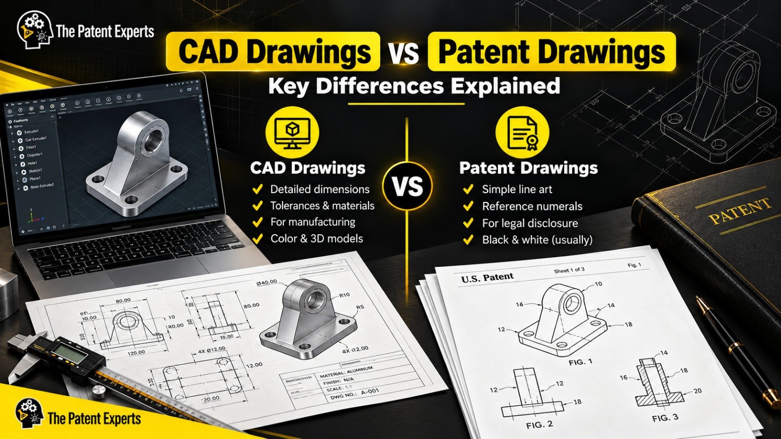
These can be excellent source materials, but they are not always ready to submit directly as patent figures.
A professional patent illustrator can convert technical source material into figures designed specifically for patent disclosure.
This is particularly valuable when the invention involves:
Multiple mechanical components
Complicated internal structures
Numerous reference numerals
Exploded assemblies
Sectional views
Multiple embodiments
Poor-quality original sketches
Tight USPTO formatting requirements
At The Patent Experts, utility patent drawings can be prepared from sketches, photographs, CAD models, technical documentation, and inventor instructions, depending on the project.
The objective is not simply to make the invention look cleaner. It is to create a drawing set that communicates the invention clearly and follows applicable USPTO drawing standards.
There is no universal set of mandatory views for every utility patent application.
The USPTO's fundamental principle is straightforward: include as many views as necessary to show the invention clearly.
For one invention, that may mean a perspective view, front view, and sectional view.
For another, it might require an exploded assembly, multiple elevations, enlarged details, sectional figures, and several operational positions.
Instead of asking whether you have reached a certain number of figures, ask whether the drawing set answers the important technical questions:
What is the invention?
What are its major components?
How are they connected?
What is happening inside?
Which features matter?
How does the invention operate?
When those questions can be answered clearly from the drawings and specification together, you are much closer to a strong patent disclosure.
If you need professional utility patent drawings, USPTO-compliant patent illustrations, sectional views, exploded views, or corrected patent figures, The Patent Experts can help turn your sketches, CAD files, photographs, and technical ideas into clear patent-ready illustrations.
There is no fixed number of views required for every utility patent application. USPTO guidance requires the drawing to contain as many views as necessary to show the invention. Depending on the invention, this may involve only a few figures or a much larger drawing set.
Not automatically. Those views should be included when they help explain relevant technical features. Utility patent drawings are selected according to what is necessary to understand the invention rather than by following a universal six-view checklist.
A perspective view is not universally mandatory, but it is often extremely useful because it shows multiple surfaces and component relationships in one figure. USPTO rules expressly permit perspective views.
Use an exploded view when separating components makes their relationship or assembly order easier to understand. USPTO drawing guidance specifically permits exploded views for showing the relationship or order of assembly of parts.
A sectional or cross-sectional view is helpful when important parts of an invention are hidden inside a housing or structure. Examples include internal channels, valves, seals, bearings, shafts, chambers, or layered components.
Yes. Alternate positions may be represented when they help explain the invention. Depending on clarity, this may be done using broken lines or separate figures.
Yes. When the same component appears in multiple figures, USPTO drawing rules state that it should use the same reference character. The same reference character should not identify different parts.
Yes. Multiple clearly separated figures may appear on a drawing sheet as long as they comply with USPTO arrangement and formatting requirements. The views should be arranged clearly and should not be placed on top of or inside one another.
There is no universally required first figure, but a perspective or overall view is frequently useful because it gives the reader an immediate understanding of the invention. USPTO guidance also provides that one view should be suitable for use as the front-page illustration of the published application and patent.
Photographs are not ordinarily used as a replacement for utility patent drawings. USPTO guidance allows black-and-white photographs in circumstances where the invention cannot adequately be illustrated with an ink drawing or is shown more clearly in a photograph.
Where drawings are necessary to understand the claimed invention, USPTO guidance states that the drawing should show every feature specified in the claims. The figures and written description should therefore be planned together.
Changes to patent drawings after filing can raise important legal and procedural issues, particularly if a new figure introduces information that was not supported in the original disclosure. Applicants should discuss substantive post-filing drawing changes with a qualified patent attorney or patent agent.
This article is provided for general informational purposes only and does not constitute legal advice. Patent applicants should consult a qualified patent attorney or patent agent regarding their particular application and circumstances.

At “The Patent Experts” our team specialises in turning complex concept and ideas into exact complaint patent drawings that meet the stringent guidelines of USPTO, EPO, WIPO among other major patent offices around the globe. With over 5+ years of experience, our team of skilled illustrators are efficient in producing high quality utility designs and trademark patent drawings. By combining cutting-edge technology with a deep understanding of global patent regulations, we ensure every drawing we create is ready for seamless submission and approval.
Quicks Links
Get in touch
Our phone number
Our email address
© 2026 The Patent Expert's All Rights Reserve
Made with ♥ by Website99